Uudised

What are the methods and steps for wiring dry-type transformers?

2026-08-17 0 Jäta mulle sõnum

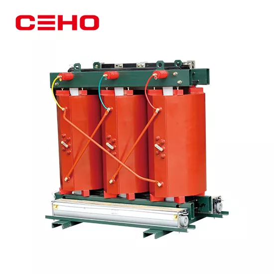
Dry-type transformers are widely used in high-rise buildings, airports, factories and other places because of their safety, environmental protection and maintenance-free characteristics. For master electricians, correct and standardized wiring is the key to ensuring the safe operation of equipment. Below, we will use easy-to-understand language to sort out the wiring methods and core steps of dry-type transformers.


I. Understand terminal blocks: distinguish between “input” and “output”

Before starting the wiring, you must first understand the labels on the transformer nameplate and terminal blocks. Dry-type transformers are usually divided into high-voltage side (input end) and low-voltage side (output end):

  • High voltage side (input): Terminals usually labeled U1, V1, W1 (or A, B, C), this is the end that connects to the external power incoming wire.
  • Low-voltage side (output): The terminals are usually identified as u, v, w (or a, b, c) and the neutral point n (or N), which is the end connected to the electrical equipment or low-voltage distribution cabinet.


II. Common wiring methods

The wiring method of dry-type transformers mainly depends on the needs of the power grid. The most common combinations are as follows:


1. High voltage side connection method:

  • Triangle connection (Δ): Connect the three-phase windings end to end to form a closed triangle. This connection method is suitable for three-wire systems without neutral points.
  • Star connection (Y): Connect the ends of the three-phase windings together to form a neutral point. This connection method is suitable for systems that need to lead out the neutral line.


2. Low voltage side connection method:

  • Star connection (Yyn0): This is the most common connection method. The output is three-phase four-wire (380V/220V), and the neutral point is directly grounded. It can provide both 380V power and 220V lighting power.
  • Dyn11 connection method: high voltage side is triangle, low voltage side is star shape. This connection method has stronger ability to suppress harmonics and better resistance to impact loads, and is currently the mainstream application method.


III. Four core steps for standardizing wiring

The first step: "physical examination" before wiring

Before formal wiring, the insulation resistance of the transformer must be tested with a megger. Short-circuit the input and output terminals and measure their insulation resistance to ground respectively. Usually, a megohmmeter with a 1000V or 2500V range is used, and the resistance must be greater than the specified standard (generally required to be greater than 2MΩ, with higher requirements on the high-voltage side) to ensure that the equipment is not affected by moisture or damage during transportation and storage.


Step 2: High-voltage side (power incoming line) wiring

Clean the high-voltage terminals to ensure that the contact surfaces are free of oxidation and dust.

Connect according to the connection method (Δ or Y) required on the nameplate. If it is a delta connection, you need to use copper bars or wires to short-circuit U1-W1, V1-U1, and W1-V1 respectively.

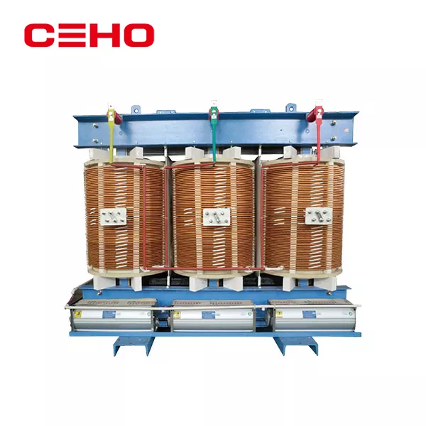
Connect the three-phase power cords (yellow, green, and red) to the U1, V1, and W1 terminals respectively.

Key point: Appropriate wire lugs or equipment clamps must be used for wiring, and tightened to the specified torque with a torque wrench to prevent heat generation caused by poor contact.


Step 3: Low voltage side (load outlet) wiring

Connect the u, v, and w terminals on the low-voltage side to the incoming circuit breaker of the low-voltage distribution cabinet respectively.

Connect the neutral point n (or N) to the neutral busbar of the low-voltage cabinet with a copper bar or wire of specified cross-section.

Key point: The current on the low voltage side is usually very high and the connection must be absolutely secure. The phase sequence must correspond to the high-voltage side (that is, high-voltage phase A corresponds to low-voltage phase a), otherwise the motor will reverse or the equipment will be damaged.


Step 4: Grounding and Safety Check

Protective grounding: The outer shell, core, and base of the transformer must be reliably connected to the grounding grid with an independent grounding wire (usually not less than 25mm² copper wire).

Working grounding: The neutral point (N line) on the low-voltage side must also be reliably grounded.

Final inspection: Confirm that all bolts are tightened, the phase sequence is correct, and there are no tools or debris left around.


IV. Warm reminder before sending power

After the wiring is completed, do not rush to run it with load. A no-load power test should be performed first to observe whether the transformer has any abnormal buzzing, sparking or odor. At the same time, check whether the temperature controller display is normal and whether the fan can start automatically when the temperature rises. After confirming that everything is normal, the load can be gradually connected.


Safety warning: The wiring of dry-type transformers is a special operation and must be performed by professionals with electrician certificates. Before operation, be sure to cut off the superior power supply, hang a "no closing" warning sign, and strictly abide by safe operating procedures!


Seotud uudised
Jäta mulle sõnum
X
Kasutame küpsiseid, et pakkuda teile paremat sirvimiskogemust, analüüsida saidi liiklust ja isikupärastada sisu. Seda saiti kasutades nõustute meie küpsiste kasutamisega. Privaatsuspoliitika
KeelduNõustu